Sun SparcStation 10 / SparcServer 10 / Axil 311


SPARCstation10

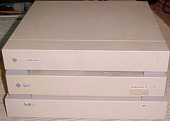
When you first spot a Sparc 10, you may mistake it for a Sparc 2, as initially, the case looks almost exactly the same as the Sparc 1 & Sparc 2 exteriors. Only upon closer examination do the differences reveal themselves. In the photo above, the topmost machine is a Sparc 2, the center machine is a Sun Sparcstation 10, and the bottom machine is the Axil 311, a Sparc 10 clone machine built by Axil/Hyundai.

The Sparc 10 was built before the Sparc 5 was, which is why Sun didn't use the "Aurora" chassis that became common for the Sparcstation 20 and the Sparcstation 5. In fact, looking at the SS10, you'd almost think that they essentially took a SS2 chassis and just squeezed a lot more computer in there.

However, as you'll see, the SS10 is a completely different breed of machine.

Hardware FAQ Info

SPARCstation 10/xx
        Processor(s):   SuperSPARC @ 33, 36, 40, 45, and 50MHz;
                        86.1-96.2 MIPS (?), see below for SPEC
        Motherboard:    501-1733/2259/2274
        Chassis type:   square pizza box
        Bus:            SBus, 4 slots and Mbus, 2 slots
        Memory:         512M physical; 32K off-chip cache for model 30,
                        1M off-chip direct-mapped cache physically
                        indexed and tagged for model 41; 1M off-chip
                        cache for models 30LC (?), 412MP, 51, 512MP,
                        514MP, 52, and 54.
        Architecture:   sun4m
        Notes:          Code name for 10/41 "Campus-2". 1.44M 3.5"
                        floppy. Up to four CPUs, some models with
                        multiple CPUs stock (two in 402MP, 412MP, and
                        512MP, four in 514MP). 16M or 64M 70ns SIMMs.

                        model  MHz  SPECint92 SPECfp92 SPECint  SPECfp
                        -----  ---  --------- -------- -Rate92--Rate92-
                        10/20  33     39.8      46.6     943     1104
                        10/30  36     45.2      54.0    1072     1282
                        10/40  40     50.2      60.2    1191     1427
                        10/402 40x2                     2112     2378
                        10/41  40     53.2      67.8    1264     1607
                        10/412 40x2                     2411     2854
                        10/51  50     65.2      83.0    1580     2008
                        10/512 50x2                     2950     3744
                        10/514 50x4                     5155     5809
		

Downloadable Documents

All documents are PDF format and require the Adobe Acrobat Reader.

pdf Sparc 10 Service Manual. Contains full disassembly and configuration details for the Sparc 10 series in general. If you have one of these machines, this document is essential.
2.3MB download.

SS10 Interior Overview

Sun Sparc 10 Interior 
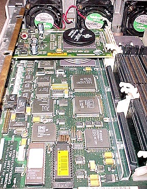
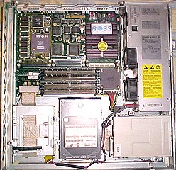
Here we're actually looking down into the Axil 311, but the machines are pretty much identical, so the major components are all in the same place. The Axil 311 is a little wider and a little deeper than the Sun branded Sparc 10, but the motherboards are the same size. The difference is that the way the Axil chassis is designed, it has a little more room around the harddrives. I prefer this, as these machines all run a little hot, and the extra room around the HD allows just a little more cooling to take place.

Sun or Axil, the SS10 can take two 50-pin SCSI harddrives, which mount with the rear of the drive facing the front of the chassis -- which is a reverse of the way the drives are mounted in the SS2. The ribbon cable then runs under the drive mounting points, and connects to a single 25 pin connection of the motherboard.

Next to the harddrives is the ubiquitous floppy drive. Which is, incedentally, one way of immediately determining a Sparc10 from a Sparc2 at a distance -- look at the side. In this image, shot from the floppy side of the machines, you'll see the Sparc2 at the top again, and you'll see the familiar round venting holes for the machine to "breathe" by pulling in air from the sides and pushing it out the back from the fan in the rear. Now look down at the Sparc10 in the center, and you'll see that Sun fashioned a wavy-side to the SS10. This "wave" is actually a series of slotted vents.

Sun changed the entire airflow pattern starting with the SS10. Look back at the interior shot, and you'll see 3 fans next to the power supply.

SS10 Airflow

airflow diagram In my rather crude diagram to the left, the first half of the image shows the typical pattern of airflow for a Sun 4x Workstation up to the creation of the SS10. In this pattern, air is typically drawn in from the left side, pulled across the motherboard, and the hot air is then expelled out the back by the fan built into the power supply.

Starting with the SS10, that pattern changed -- that air was now being drawn in from the right side of the machine, pulled across the power supply, and then pushed over the motherboard, to escape on the left side of the machine. Where you previously had to be careful not to block the left side of your workstation, you now had to be careful not the block either side of your workstation for the best cooling.

One problem I must note with this new airflow pattern is that the motherboard edge closest to the fans gets a lot of dust build-up on it. Components on that side quickly get a coating of crud, and that can also lead to improper cooling. And considering that in some cases, two or four hot CPUs can be in the path of those fans, it's important to keep your machine clean.

It may be difficult to understand what you're looking at from these images, but the big thing with the ROSS label is a CPU and heatsink that is connected to an MBUS connector, and actually sits above the motherboard. There's a second MBUS connector right behind the first one, which allows two CPU modules to be stacked one on top of the other. When you use single CPU modules, you can only get 2 CPUs into an SS10. If you want to get 4 CPUs, then you need to obtain dual CPU MBUS modules, as there are only two MBUS connectors.

Obviously; sitting the CPUs right next the the fans was intentional on the part of the designers, as a 4 CPU SS10 will run extremely hot.

SS10 Rear Ports

Rear Ports 
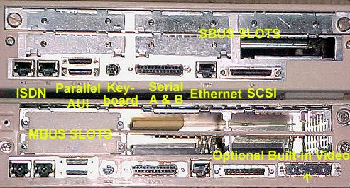
Sorry, I reversed everything! In this image, the Axil 311 is on top and the Sun SS10 is the lower half of the image. And except for a single difference, the two have an identical set of ports on the rear.

Starting from the left, the first set of ports are two RJ-54s for ISDN connections. Then, there are two ports one above the other. The topmost port is Parallel, and the port below it is AUI. Next comes the round Mini-Din for the Keyboard.

Then we have a standard DB-25 port which contains a mixed serial "A" and serial "B". If you want to use serial "A", a standard serial cable will work just fine, but serial "B" can only be accessed with a special "Y-splitter" type serial cable (unless you want to make your own cables).

Next is a very standard 10base-T Ethernet RJ-45 port. And almost last is the HD-50 SCSI port.

Now, on the Sun SS10, there's an optional built-in video port. Mine has no connector, but it looks like some models of the S10 may have come with a built-in framebuffer. The SS20, which came later, also had such a port, but it could only be used when special memory was intserted into the SS10 which "bridged" the main memory and the VRAM -- my guess is that the SS10 worked (or was being planned to work) the same way.

You'll also notice the MBUS slots and the SBUS slots. If you look sharply, you'll notice that on both machines, the upper row of slots, regardless of what they are (i.e. MBUS or SBUS), are indented. This is because, as I had stated above, that in order to squeeze in 2 CPUS and 4 SBUS cards, the connectors for the upper row are behind the connectors for the lower row -- so the metal of the chassis needed to be "indented" to accomodate the length of the card, sitting slightly above and slightly behind the card below it.


All About the MBUS

ss10 mobo ss10 mobo

These above-left image of the motherboard shows the Sparstation 10 with the MBUS CPU module inserted in the first MBUS slot, while the right image shows the motherboard with the CPU module removed.

The very crudely drawn red arrows show the first and second MBUS connectors, and the yellow arrows indicate the four SBUS connectors. Note the two-tiered method used to "stack" cards one-ontop of the other. This is what allows the SS10 and the later SS20 to hold four SBUS cards, as well as two MBUS modules.

ss10 cpu 
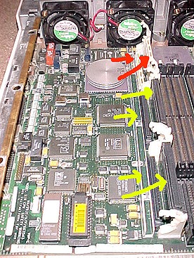
You can place up to 4 CPUS in a SS10, but that requires that each MBUS module to hold 2 CPUs, essentially the first MBUS slot handles processors zero and one, while the second slot handles processors two and three. If you have a single CPU module installed in each slot, it will show up as processors zero and two, NOT zero and one.

The single CPU module shown here to the left is more typical of what you'd find in your average SparcStation 10. The CPU is the big square chip with the circular heatsink. A dual-CPU module would (obviously) feature two of these chips and heatsinks. Be aware that if you're psycho enough to install four CPUs in your SS10, you'd better be working in a refrigerated environment as the SS10 will get really, really hot with 4 CPUs crammed in there.

Also, a note about later modules, such as the SM51, is that they had the chip's cache on a seperate chip that was also heatsinked -- so don't confuse those with a dual CPU MBUS module.

Common Mbus Modules 
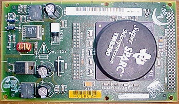
So that I can clear up some confusion regarding MBUS modules, I've included an image which shows the outlines of several types of modules. Note that the dual-CPU module is double width -- meaning that if you install this module, you'll block off one of your SBUS slots - and therefore when you install two dual-cpu modules, you cut off two of your SBUS connectors (then limiting the SS10 to two remaining SBUS cards).

The SM51's were generally a round heatsink for the CPU and a square heatsink for the cache, while the SM61's shared a heatsink between the two chips. Previous to the SM51 (such as the SM40) didn't feature the cache on a seperate chip -- however, these are just generalizations to help you visually identify an MBUS module if you see one lying on a table at a swap-meet.

There are some instances where what I've said may not apply -- ALWAYS check the part number to find out what you're really holding in your hand! For example, after doing a little checking, I can tell you that the SM520 doesn't even work in an SS10!

More to come soon!